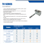
Operating within air ducts across the globe, Firestat duct controls play an important role in HVAC systems, ensuring safety by halting equipment if air temperatures exceed pre-set limits. These switches are key in specialized HVAC setups and Building Automation Systems (BAS).
For additional help installing your Firestat, contact us.
What Is a Duct High Limit Switch?
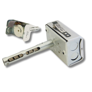
A duct high limit switch (often called a Firestat) is a manual reset temperature safety control that monitors the air temperature inside HVAC ductwork. When temperatures exceed the preset limit, the switch interrupts power to the heating equipment, blower, or other connected devices to help prevent overheating and reduce the spread of heat and smoke through the duct system.
Firestat duct high limit controls are commonly installed in:
- Apartment buildings
- Commercial HVAC systems
- Electric duct heaters
- Air handlers
- Rooftop units
- Schools
- Hospitals
- Building Automation Systems (BAS)

Why Install a Firestat?
A properly installed duct high limit control provides an independent mechanical safety device that operates even if the building automation system or electronic controller fails.
Benefits include:
- Protects HVAC equipment
- Helps reduce fire spread
- Meets many mechanical code requirements
- Protects occupants
- Simple mechanical operation
- No external power required
Before You Begin
Before installation verify:
- Correct temperature range
- Proper probe length
- Voltage rating
- Wiring diagram
- Mounting location
- Local code requirements
Step 1: Choose the Correct Installation Location
The sensing element should be installed where abnormal temperatures would occur first.
Typical locations include:
- Downstream of electric heating elements
- Supply ducts leaving heating equipment
- Return air ducts near heat sources
- Areas near combustible construction
The sensing probe should extend into the duct airflow while keeping the enclosure mounted outside the duct.
Step 2: Mount the Firestat
- Mark the mounting location.
- Drill the required opening.
- Insert the sensing element.
- Secure the housing.
- Confirm the probe is fully exposed to airflow.
Avoid mounting where stagnant air could delay temperature detection.
Step 3: Wire the Control
Firestat controls may be used in both:
- Low-voltage control circuits
- Line-voltage control circuits
Many installations are wired to interrupt both:
- Heat source
- Blower circuit
When multiple Firestats protect the same equipment, wire them in series so any activated switch shuts the system down.
Always follow the supplied wiring diagram.
Step 4: Set the Temperature
Every Firestat ships preset to 125°F, but adjustable models can be set between 100°F and 250°F.
To determine the correct setting:
- Operate the HVAC system normally.
- Measure the duct temperature near the installation point.
- Add approximately 40°F.
- Set the Firestat to that value.
This provides protection while minimizing nuisance trips.
Step 5: Adjust the Temperature Dial
Adjusting the switch is simple:
- Remove the cover.
- Loosen the adjustment screw.
- Rotate the selector to the desired temperature.
- Tighten the screw.
- Replace the cover.
Step 6: Test the Installation
After installation:
- Run the HVAC system.
- Verify normal operation.
- Heat the sensing element carefully to confirm the switch trips at the selected temperature.
- Reset the switch manually.
- Confirm normal operation resumes.
Routine testing helps verify continued operation over the life of the installation.
How to Test Your Duct High Limit Switch
Installing a duct high limit switch is only the first step. Before placing your HVAC system into service, you should verify that the Firestat operates correctly. Regular testing also helps ensure the switch continues to provide reliable protection throughout its service life.
Although every Firestat is factory tested before shipment, performing a functional test after installation confirms that the switch has been wired correctly and responds at the desired temperature. Periodic testing is also recommended as part of your building’s preventative maintenance program.
Step 1: Verify the Installation
Before testing, confirm that:
- The Firestat is securely mounted.
- The sensing probe extends properly into the duct airflow.
- Wiring matches the supplied wiring diagram.
- The desired temperature has been set.
- The HVAC system is operating normally.
Step 2: Raise the Probe Temperature
Carefully increase the temperature surrounding the sensing element until it exceeds the selected trip temperature.
This can be accomplished using an approved heat source while following all applicable safety procedures.
Never use an open flame directly on the sensing element.
The goal is simply to simulate an over-temperature condition.
Step 3: Verify System Shutdown
As the probe temperature exceeds the set point, the Firestat should immediately change the contact state.
Depending on your application, this may:
- Shut down the blower
- Disable the heating equipment
- Close dampers
- Signal a building automation system
- Interrupt another connected safety circuit
If the connected equipment does not respond, inspect the wiring before placing the system into service.
Step 4: Allow the Firestat to Cool
Once the switch has tripped, allow the sensing element to cool below the selected temperature.
The manual reset mechanism cannot be reset while the sensing element remains above the trip point.
Step 5: Perform the Manual Reset
After cooling:
- Lift the manual reset lever.
- Allow it to snap back into place.
- Verify that the contacts have reset.
- Restart the HVAC system.
- Confirm normal operation.
The manual reset feature requires someone to physically inspect the system before restarting the equipment. This helps ensure that the cause of the over-temperature condition has been identified and corrected before the HVAC system returns to operation.
How Often Should You Test a Firestat?
For maximum reliability, we recommend:
- Testing after every new installation
- Testing after any maintenance affecting the HVAC controls
- Testing annually as part of preventative maintenance
- Testing whenever improper operation is suspected
Routine testing helps verify that the sensing element, switch mechanism, and wiring continue to operate correctly throughout the life of the system.
Troubleshooting a Firestat That Doesn't Trip
If the switch does not operate during testing, check the following:
Problem
Possible Cause
Switch does not trip
Temperature did not exceed the set point
Equipment continues running
Incorrect wiring
Trips too early
Temperature setting too low
Trips too late
Probe not centered in airflow
Will not reset
Probe has not cooled below the reset temperature
Inconsistent operation
Probe length may be incorrect for the duct size
Preventative Maintenance Tips
Common Installation Mistakes
To maximize the life and reliability of your Firestat:
- Inspect the probe during routine HVAC service.
- Verify the sensing element is clean and undamaged.
- Confirm all wiring remains secure.
- Check that the reset mechanism operates freely.
- Verify the temperature setting has not been altered.
- Function-test the switch according to your maintenance schedule.
Avoid these common issues:
- Installing upstream of the heat source
- Incorrect temperature setting
- Wiring only the blower
- Wiring multiple switches in parallel
- Using the wrong probe length
- Mounting where airflow is restricted
Firestat Specifications
Typical specifications include:
Feature | Specification |
Temperature Range | 100°F–250°F Adjustable |
Factory Setting | 125°F |
Reset | Manual |
Probe Lengths | 5″, 7.5″, 11″ |
Applications | Low and Line Voltage |
Certifications | UL/cUL |
Frequently Asked Questions
Does the Firestat automatically reset?
No. Firestat controls require manual reset after an over-temperature event. If an automatic switch was used and returned the HVAC system back to normal state too soon, it could cause the potential fire to be spread throughout the building.
Can multiple Firestats protect one unit?
Yes. Wire them in series.
What temperature should I use?
Normal operating temperature plus approximately 40°F.
Can it be used with Building Automation Systems?
Yes. Firestat controls are commonly integrated into BAS as an independent mechanical safety device.
Is it compatible with line voltage?
Yes. Firestat controls are available for both low-voltage and line-voltage applications.
Need Help Selecting the Right Firestat?
Whether you’re protecting an apartment complex, commercial building, electric duct heater, or industrial HVAC system, our team can help you select the proper duct high limit control for your application.
Browse our Adjustable and Fixed Temperature Firestat models or contact our technical support team for assistance.