A duct high limit switch is a temperature-sensitive device that disables HVAC fans, blowers, or heat sources when duct air temperatures exceed a configured threshold. Installing this switch in a ducted HVAC system provides a mechanical method for isolating heat sources during abnormal thermal conditions. This duct temperature high limit installation guide outlines placement, wiring, temperature setting, and adjustment procedures for Firestat high limit controls in commercial and residential systems.
View full product line of Firestat duct temperature high limit switches or contact us for OEM pricing.
 Placement and Mounting for Duct Temperature High Limit Installation
Firestat controllers are designed to mount externally on HVAC ducts in airflow zones likely to experience temperature elevation. Ideal installation points include:
-
Downstream of electric heating coils
-
Return ducts near equipment rooms
-
Supply ducts adjacent to high-temperature components
Controllers should always be positioned in the direction of airflow to ensure consistent thermal exposure.
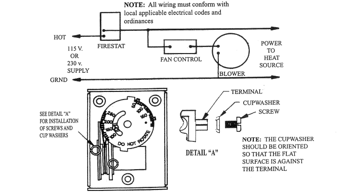 Electrical Wiring and Voltage Compatibility
Firestat switches support both low voltage and line voltage applications. During duct temperature high limit installation, confirm that:
-
The device interrupts both the blower and heat source circuits
-
Multiple switches wired to one heat source are connected in series
-
Circuit protection is compatible with the controller’s current and voltage ratings
Correct wiring ensures that a high-temperature event will cut power to airflow and heating equipment simultaneously.
Setting the Temperature Limit
Each Firestat unit comes factory-set to 125°F but allows adjustment between 100°F and 250°F. To determine the correct limit:
-
Measure Active Temperature: Run the HVAC system under normal load and measure duct temperature near the installed switch.
-
Apply Margin: Add 40°F to the measured value to define a safe shutoff threshold.
This method prevents premature activation while providing a buffer for temperature spikes.
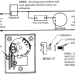
Adjusting the Temperature Dial
To adjust the setpoint on a Firestat switch:
-
Remove the Cover: Press the sides of the housing to release the cover.
-
Set the Temperature: Loosen the screw, rotate the dial to the desired temperature, and retighten.
-
Reinstall: Replace the cover and confirm alignment before securing the switch on the duct.
This adjustment process allows field technicians to tailor each unit to system-specific thermal behavior.
Specifications for Integration
Firestat duct high limit switches meet a range of HVAC control and safety requirements:
-
Temperature Range: Adjustable 100°F–250°F
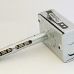
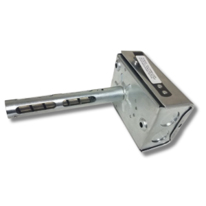
-
Probe Length Options: 5″, 7.5″, or 11″ bi-metal sensing elements
-
Operating Environment: Enclosure -40°F to 190°F; sensing element rated to 350°F
-
Configuration Options: Custom labeling and OEM designs available for specific control panel layouts
These specifications support integration in packaged rooftop systems, fan coils, air handlers, and automation-controlled duct systems.
Application Use Cases
Duct temperature high limit installation supports fire safety, equipment protection, and code compliance in:
-
HVAC systems with electric reheat or resistance coils
-
Multi-zone systems in commercial buildings
-
Multi-family residential fan coils
-
Facilities governed by mechanical or fire protection codes
-
BAS networks requiring mechanical fallback during controller failure
Firestat devices provide mechanical shutoff functionality independent of software or digital controls.
Firestat Installation in Safety-Driven HVAC Systems
Duct temperature high limit installation provides HVAC systems with a mechanical safeguard against overheating. Firestat switches detect rising duct air temperature and open the circuit when setpoints are exceeded, stopping airflow and heat generation. Proper installation, wiring, and configuration ensure these devices function as intended in demanding environments.
To download a PDF version of this technical guide on duct temperature high limit installation, click here.